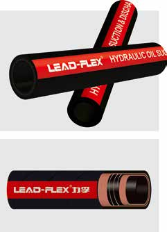
Fluid dynamics shift dramatically as ambient temperatures drop. Cold hydraulic oil presents a serious engineering challenge due to its exponentially higher viscosity. This extreme fluid thickness forces pumps to work excessively hard to draw oil from the reservoir. You face massive equipment risks in these sub-zero conditions. Pump starvation and cavitation rank as the primary threats in cold weather applications. Undersizing an inlet line during low-temperature operation leads directly to premature pump failure. It also causes severe fluid aeration and critical system downtime. You must treat sub-zero environments entirely differently than standard operating applications. Standard sizing methods often fail miserably in freezing climates. This guide provides a definitive, step-by-step engineering framework to solve this challenge. You will learn how to correctly calculate, specify, and route these critical components for cold oil environments. We will walk you through viscosity impacts, velocity adjustments, and precise fitting selection to ensure maximum system reliability.
Key Takeaways
Cold oil requires a significantly lower flow velocity (often targeting 2 ft/sec or lower) compared to standard suction applications to compensate for high fluid viscosity.
Inside Diameter (ID) must typically be upsized by at least one standard Dash size when operating consistently in sub-zero or cold-start conditions.
A true hydraulic suction hose must feature a helical wire reinforcement to prevent vacuum collapse under heavy draw.
STAMPED criteria (specifically Temperature, Material, and Pressure/Vacuum) must be adjusted for extreme low-temperature flexibility (e.g., -40°C to -50°C ratings).
The Impact of Cold Oil on Suction Line Dynamics
Operating machinery in freezing temperatures changes the physical properties of your fluids entirely. You must understand how thermal changes affect flow dynamics to prevent catastrophic equipment damage.
Viscosity vs. Temperature Curve
Kinematic viscosity measures fluid resistance to internal flow. It correlates inversely to temperature variations. Viscosity spikes aggressively as temperatures plummet below freezing. Oil transforms from a smooth, fast-moving liquid into a thick, syrup-like substance. This physical transformation increases internal fluid friction massively. Thick oil resists moving through a standard hydraulic hose. Fluid drag increases significantly along the inner tube walls. The pump must expend extra energy just to pull this thick mass forward. You cannot rely on warm-weather flow rates when analyzing a cold system.
The Threat of Cavitation
Pump starvation happens when fluid cannot reach the inlet fast enough. The hydraulic pump pulls fluid aggressively from the reservoir. However, viscous oil flows too slowly to fill the mechanical void. This volume imbalance creates an extreme vacuum inside the line. System pressure drops rapidly below the vapor pressure of the fluid. Vapor bubbles form instantly inside the moving fluid stream. These microscopic bubbles travel into the high-pressure side of the pump. They implode violently against internal metal surfaces. You can often hear this phenomenon; it sounds like marbles rattling inside a tin can. These microscopic explosions tear away metal particles. They destroy internal pump components rapidly and permanently.
Why Standard Sizing Fails Here
Many engineers rely on standard industry nomograms to size fluid lines. These traditional charts contain a fatal flaw for cold environments. They assume your fluid sits at an ideal, warm operating temperature. Standard operating ranges usually fall between 100°F and 140°F (38°C to 60°C). Using these normal charts for cold starts guarantees a massive sizing error. You will end up specifying a completely undersized line. An undersized line chokes the pump inlet immediately upon a cold startup. The pump starves before the oil ever has a chance to warm up.
Common Mistake: Ignoring the cold-start window. Engineers often size lines for the machine's continuous operating temperature. However, the most severe pump damage occurs during the first ten minutes of a freezing morning cold start.
Calculating the Inside Diameter (ID) for Cold Viscous Fluids
Proper sizing requires a deliberate shift in your calculation methodology. You must prioritize minimum flow resistance over physical compactness.
Target Flow Velocity
Velocity dictates how fast fluid travels through a conduit. The standard industry rule of thumb targets 2 to 4 feet per second for inlet applications. In metric units, this equals 0.6 to 1.2 meters per second. Cold oil requires a drastic mathematical adjustment. You must anchor your calculation at the absolute minimum velocity limit. Target 2 ft/sec or even slower. Lower velocity reduces friction loss inside the tube dramatically. It allows thick oil to travel smoothly toward the pump inlet without creating a harsh vacuum.
The Nomogram Method (Adjusted)
You can still use standard nomograms if you adjust your inputs appropriately. Follow these specific steps to calculate the correct diameter for cold fluids:
Identify Maximum Flow: Determine your absolute maximum pump flow rate in gallons per minute (GPM) or liters per minute (LPM).
Set the Velocity Limit: Look at the velocity column on the nomogram. Do not pick a middle-ground velocity. Mark a strict, non-negotiable point at the 2 ft/sec (0.6 m/s) mark.
Draw the Intersect: Draw a straight line between your maximum flow rate and this strict low-velocity point.
Read the ID: The exact point where this straight line crosses the center column gives you your minimum Inside Diameter.
Dash Size Translation
Industry standards use "Dash sizes" to represent fluid tube measurements. Dash sizes indicate sixteenths of an inch. A calculated ID rarely lands on a perfect whole number. Always round up to the next largest standard Dash size. If your calculation dictates a 1.2-inch ID, do not size down to 1 inch. Move up to a -24 (1.5 inch) size to ensure adequate flow.
Hydraulic Hose Dash Size Translation for Suction Lines
Dash Size
Inside Diameter (Inches)
Inside Diameter (Millimeters)
Typical Cold Application
-12
3/4"
19.0 mm
Low flow gear pumps
-16
1"
25.4 mm
Medium flow mobile equipment
-20
1-1/4"
31.8 mm
Heavy duty mobile equipment
-24
1-1/2"
38.1 mm
High flow industrial systems
-32
2"
50.8 mm
High-capacity reservoir feeds
Applying the STAMPED Framework to Cold Weather Suction Hoses
The STAMPED framework (Size, Temperature, Application, Material, Pressure, Ends, Delivery) guides professional component selection. Cold environments require specific adjustments to several of these core criteria.
Size (ID, OD, and Length)
You must keep the inlet line incredibly short. Mechanical equipment layouts often force awkward, long routing paths. Avoid this trap at all costs. Keep the path as straight and direct as mechanically possible. Long runs increase volumetric drag drastically. More drag means higher vacuum pressure at the pump inlet. A properly sized hydraulic suction hose still fails if you route it excessively long. Every extra foot of length compounds friction losses.
Temperature & Material
You must distinguish clearly between ambient air cold and fluid cold. Machines might sit in -40°F air all night. The oil inside drops to this exact ambient temperature before startup. You need specific cold-weather elastomers to handle this reality. Specialized NBR (Nitrile) or EPDM rubber blends handle these extremes beautifully. Standard rubber compounds become brittle, stiffen, and crack under stress. Cold-rated materials maintain structural flexibility down to -40°F (-40°C) or even -70°F (-57°C). They prevent jacket embrittlement during freezing startups.
Pressure (Vacuum Rating)
Engineers often focus entirely on positive working pressure when designing systems. Inlet lines operate on negative pressure instead. You evaluate them based strictly on vacuum capacity, usually measured in inches of Mercury (inHg). A true suction hose must resist collapsing inward. You must confirm it features a helical wire reinforcement. This rigid steel wire spirals continuously through the rubber carcass. It prevents the outer jacket from flattening under heavy vacuum loads. Without this wire, the tube sucks shut like a flimsy plastic straw.
Fittings, Connections, and Flow Restrictions
The rubber tube represents only one part of the inlet equation. Metal connection points often create severe hidden bottlenecks that destroy system efficiency.
Evaluating Fitting IDs
Fluid does not just flow through the flexible rubber tube. It travels through steel fittings at both ends. The internal diameter of a metal fitting often measures much smaller than the rubber tube ID. This dimensional difference creates a hidden restriction. A -16 rubber tube might utilize a fitting that mimics a -12 flow footprint. This sudden restriction accelerates fluid velocity locally. It triggers immense pressure drops right at the connection point. You must verify the actual bore size of the metal fittings before installation.
Avoiding Turbulence
Sharp metallic turns create severe turbulent flow. Fluid turbulence destroys pump efficiency and increases aeration risks. Avoid 90-degree threaded elbows entirely in inlet applications. Recommend sweeping bends or 45-degree angle fittings instead. Use flanged connections like SAE Code 61 or Code 62 wherever possible. Flanges provide a smooth, full-flow transition between components. They minimize turbulence and eliminate unwanted pressure drops. Threaded NPT fittings often restrict flow heavily and should be avoided on cold inlet lines.
Best Practices for Inlet Connections:
Always measure the internal bore of the fitting using digital calipers.
Avoid step-down adapters; they create immediate fluid bottlenecks.
Ensure flange mating surfaces are perfectly clean to prevent vacuum leaks.
Use long-drop swept elbows instead of forged block elbows.
Seal Compatibility in the Cold
Extreme cold shrinks rubber seals predictably. Standard O-rings contract significantly inside their metal grooves. This thermal shrinkage creates microscopic gaps between mating surfaces. High vacuum pulls ambient air directly through these gaps. Air ingress causes severe system aeration, leading to spongy hydraulics and poor actuator response. Recommend cold-rated seal materials always. Use low-temperature nitrile or specialized fluorocarbon seals. These specific compounds maintain their volume and ensure airtight integrity even in deep freezes.
Implementation Risks and Routing Best Practices
Designing the system correctly on paper means nothing if you install it poorly. Cold environments dictate strict physical handling and routing rules.
Bend Radius Restrictions
Cold elastomers turn incredibly stiff. Bending them requires excessive physical force. Forcing a tight bend radius creates immediate mechanical problems. It causes localized kinking along the inner rubber wall. It also induces severe internal stress on the steel reinforcement layers. Kinking restricts flow capacity instantly and permanently damages the tube structure. Always adhere strictly to maximum bend radius guidelines published for low temperatures. Never force a cold assembly into a tight corner.
Hose vs. Pipe Considerations
Engineers often debate using rigid steel tubing versus flexible alternatives. Rigid steel pipes offer excellent, smooth flow characteristics. They absolutely do not collapse under vacuum. However, mobile machines and industrial power units vibrate heavily. Recommend flexible solutions only where vibration isolation proves strictly necessary. Use them to accommodate mechanical articulation or pump movement. Keep the flexible segment as short as possible to minimize fluid drag. Use rigid steel pipe for the long, straight runs back to the reservoir.
Pre-heating Considerations
Sometimes upsizing diameters fails to solve extreme fluid viscosity. Sub-zero climates render some heavy oils completely unpumpable regardless of pipe diameter. Consider complementary heating solutions when facing these extremes. Suggest electric immersion heaters placed directly inside the fluid reservoir. You can also implement warm-up circulation loops using low-pressure auxiliary pumps. Pre-heating drops oil viscosity back into a safe, pumpable range before you ever engage the main workloads. This strategy protects the primary pump from initial cold-shock cavitation.
Conclusion
Exact diameter sizing guarantees pump survival in cold operating conditions. You must manage fluid flow velocity tightly to ensure success. Keep internal speeds well below two feet per second to compensate for high viscosity. Remember the harsh financial reality of hydraulic failures in the field. Upsizing rubber components and optimizing metal fittings costs very little upfront. Optimizing these connections prevents expensive, catastrophic damage later. Replacing a cavitated primary pump costs thousands of dollars in replacement parts, labor, and unscheduled downtime. Do not guess on critical inlet dimensions. Consult your specific application specs thoroughly before ordering components. Speak directly to a technical sales engineer to verify your nomogram calculations. Finally, always verify material compatibilities to ensure your system survives the deep freeze.
FAQ
Q: What is the maximum flow velocity for a hydraulic suction hose?
A: Generally 4 ft/sec for standard systems, but should be kept under 2 ft/sec for cold or highly viscous oil.
Q: Can I use a standard return line hose for suction applications?
A: No. Return lines lack the helical wire reinforcement necessary to prevent collapse under vacuum.
Q: How do I convert a hydraulic hose Dash size to actual inches?
A: Dash sizes represent 1/16th of an inch. Example: -16 is 16/16, or 1 inch ID.
Q: What happens if my suction hose is too long?
A: Increased friction and pressure drop, multiplying the risk of pump cavitation, especially with cold fluids.