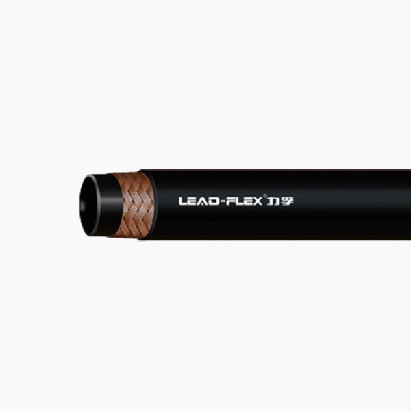
Exceeding the minimum bend radius frequently causes premature failure in fluid routing systems. Forcing flexible lines into impossibly tight spaces creates severe operational hazards for industrial machinery. A fiber braided hydraulic hose provides superior flexibility and significant weight advantages over heavier wire-reinforced alternatives. Yet, accurate measurement of its bend radius remains entirely non-negotiable for safe, reliable system design. Ignoring these limits invites catastrophic blowouts and expensive machinery downtime.
Our comprehensive guide delivers the exact methodology for measuring and evaluating these essential components. Engineers, maintenance teams, and procurement professionals will learn how to properly specify lines for tight-routing environments. You will discover practical steps to prevent leaks, optimize routing geometry, and extend overall equipment life safely.
Key Takeaways
Industry standard (SAE) bend radius is measured from the inside edge of the curvature, not the centerline or outside edge.
Minimum bend radius dictates the tightest curve a hose can safely make at its maximum operating pressure without risking internal damage or restricting flow.
Dynamic applications require a larger bend radius than static installations to accommodate pressure surges and movement.
Specifying the correct fiber braided hydraulic hose requires balancing minimum bend requirements with operating temperatures and fluid compatibility.
The Financial and Operational Impact of Correct Bend Radius
Forced bends severely compromise the structural integrity of internal reinforcements. Manufacturers typically use synthetic textiles like polyester or nylon for the fiber braid. Bending these materials beyond their physical limits creates immense uneven stress. Outer layers stretch dangerously thin under tension. Inner layers compress, buckle, and fold inward. This hidden distortion ruins the engineered structural balance. You must prioritize correct routing geometry during installation.
Correct routing features distinct success criteria. It guarantees zero kinking during high-pressure operation. It maintains the original inner diameter perfectly throughout the curve. This consistency ensures an optimal fluid flow rate. Improper bend radiuses in a hydraulic oil delivery hose cause specific, expensive failures. You will typically encounter these critical failure modes:
Localized pressure spikes and heat buildup: Restricted flow creates excessive friction and dangerous fluid temperatures.
Tube collapse and pump cavitation: Flattened lines starve pumps of fluid, causing severe mechanical damage.
Unexpected downtime and fluid spill hazards: Ruptured braids lead to immediate system failure and environmental contamination.
The Standard Methodology: How to Measure Bend Radius Accurately
Industry guidelines dictate a specific measurement anchor point. You must follow the baseline rule carefully. Standards require measuring the radius of the circle created by the innermost edge of the bent line. You must never measure from the outside jacket. We rely on this inner-edge metric to ensure the tube remains fully open.
The formal measurement process requires precision. Follow this standard formula to find the exact minimum radius:
Step 1: Form the line into a natural U-shape without forcing or flattening it.
Step 2: Measure the exact distance between the two parallel straight ends of this U-shape.
Step 3: Divide this measured distance by two (Distance ÷ 2 = Minimum Bend Radius).
Many novices mistakenly measure from the centerline. Centerline measurements include half of the hose diameter in the calculation. This common error overestimates true flexibility. It leads directly to dangerous routing errors in tight spaces. You must strictly use the inner edge to guarantee operational safety.
Dynamic vs. Static Applications: Implementation Realities
Static installations involve lines fixed in one permanent position. They do not move during machine operation. Baseline manufacturer specifications typically reflect these static minimums. They assume zero mechanical movement. You can safely route a static line right up to its published bend limit.
Dynamic installations tell a completely different operational story. Continuous flexing heavily alters the structural tolerance of the fiber reinforcement. Engineering standards require necessary adjustments for moving parts. Dynamic applications often require increasing the minimum bend radius by up to 20-30% above the static rating. This extra allowance prevents premature fatigue in the synthetic yarns.
Pressure surges complicate dynamic applications further. High pressure physically changes the assembly dimensions. The line shrinks in length under sudden pressure spikes. It simultaneously expands in diameter. This physical change naturally tightens the existing bend. A curve that looks perfectly safe at zero pressure may kink violently during a sudden surge. You must design for the pressurized state.
Variables That Compromise Fiber Braided Hose Flexibility
Temperature extremes drastically alter physical material properties. Cold environments stiffen the inner elastomer tube significantly. This makes the assembly much harder to bend safely. You risk cracking the cold tube if you force a tight bend. Conversely, excessive heat degrades the textile fiber braid over time. This thermal degradation reduces the safe bend radius permanently.
Fluid compatibility also plays a massive role in flexibility. Improper pairing of synthetic fluids causes the inner tube to swell. Swollen tubes restrict internal flow capacity. They also increase kinking risks at standard radiuses. You must verify chemical compatibility before finalizing your routing design.
External abrasions pose another significant mechanical threat. Tight bends push lines hard against sharp machine components. Friction wears away the outer protective cover rapidly. You often need protective external sleeving to prevent wear. However, adding rigid sleeving further restricts overall flexibility. Selecting a robust Hydraulic Hose requires accounting for these compounding variables. You must balance abrasion resistance with bending capabilities.
Routing Best Practices and System Design Evaluation
Engineers must evaluate system design thoroughly before cutting materials. We strongly recommend the strategic use of steel adapters. Use 45° or 90° standard fittings to accommodate severe angles. Do not bend the flexible assembly beyond its rated capacity. Adapters eliminate dangerous stress points instantly. They provide a much safer fluid path in confined areas.
The plane of flexing represents another critical design rule. You must avoid torsional stress entirely. Bending must always occur in a single, distinct plane. Twisting the assembly during installation destroys it quickly. Twisting a line by just 5 degrees can reduce its lifespan by 70%. You should use printed laylines as a visual guide to ensure zero twist.
You must also allow for operational slack. Never pull a line completely taut between two connections. Always leave sufficient slack during the initial installation phase. A 2-4% allowance of total length absorbs operational contraction perfectly. This slack accommodates pressure surges without stressing the end fittings.
Procurement Checklist: Specifying the Right Hose for Tight Routings
Buyers must compare standard versus half-bend specifications carefully. Standard SAE 100R3 or SAE 100R6 lines work perfectly well for general use. However, specialized low-profile alternatives offer better solutions for incredibly tight spaces. These modern variants use advanced textile braiding techniques. They achieve much tighter bends without sacrificing pressure ratings.
Table: Standard Specifications Evaluation Criteria
Specification Feature
Standard SAE 100R6
Specialized Low-Profile Hose
Primary Benefit
Bend Radius Limit
Standard industry baseline
Up to 50% tighter than baseline
Fits compactly into modern machinery
Textile Braid Material
Standard polyester yarns
High-tensile engineered synthetics
Maintains shape under severe curves
Outer Cover Profile
Standard thickness
Abrasion-resistant thin cover
Reduces outer diameter footprint
You need a solid vendor evaluation framework. Ask if the manufacturer provides verified test data freely. They should offer data for both static and dynamic minimums. Check if their production tolerances strictly comply with SAE, DIN, or EN standards. Certified compliance ensures predictable bending performance in the field.
For next steps, buyers should logically shortlist potential suppliers. Gather your exact spatial dimensions first. Document your peak operating pressures and expected machine duty cycles. Compile all this environmental data clearly. Submit this complete profile before requesting a quote or engineering sample. This guarantees you receive the correct flexible solution.
Conclusion
Accurately measuring the bend radius from the inner edge is a fundamental requirement for system safety. Relying on centerline measurements creates false confidence and invites catastrophic failures. We strongly advise prioritizing correct routing geometry above all else. Use proper angled fittings rather than simply forcing a flexible line into a tight space.
Engineers must respect the physical limits of synthetic textile reinforcements. Account for pressure surges, extreme temperatures, and dynamic flexing during the design phase. We encourage you to consult directly with technical sales teams. Reference OEM specification charts meticulously to select the exact component for your spatial and pressure constraints. Proper specification ensures reliable operation, prevents costly downtime, and guarantees workplace safety.
FAQ
Q: What happens if I exceed the minimum bend radius on a fiber braided hydraulic hose?
A: Exceeding the limit flattens the hose, restricts fluid flow, increases system heat, and causes the internal textile braids to separate, leading to imminent rupture.
Q: Can I use a wire braided hose if I need a tighter bend radius?
A: Generally, no. Fiber braided hoses are inherently more flexible than wire braided hoses of the same diameter. If a standard fiber braided hose cannot make the bend, you likely need a specialized compact hose or a rigid angled fitting.
Q: Does the size (ID/OD) of a hydraulic oil delivery hose affect its bend radius?
A: Yes. As the inner diameter (ID) and outer diameter (OD) increase, the minimum bend radius also increases exponentially. Larger hoses require significantly more space to route safely.
Q: How do I calculate the minimum length of hose required to make a 90-degree bend?
A: Use the standard formula: Length = (Minimum Bend Radius × 2 × π) / 4. Add the straight lengths required for the couplings on both ends to determine the total cut length.