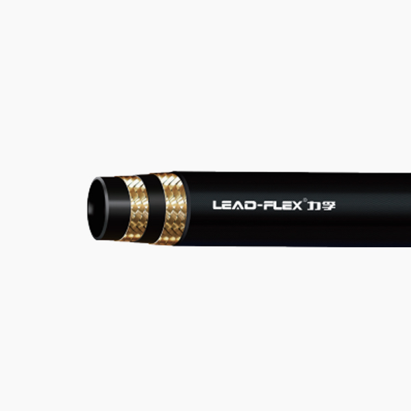
Modern mobile equipment packs more hydraulic power into increasingly smaller frames. You often face the difficult task of routing fluid power lines through severely restricted spaces. This high-density packaging creates a major challenge for engineers and technicians alike. Forcing standard hoses into tight envelopes leads to disastrous results. You risk premature hose failure and dangerous system leaks. Unwanted pressure drops occur frequently. Manufacturers will promptly void your equipment warranties if installation limits are ignored. We must find a better approach for these demanding environments. You need to understand how the minimum bend radius of a Compact Hydraulic Hose prevents catastrophic system failure. This article explores the precise engineering behind these specialized fluid lines. You will learn how to evaluate different reinforcement types effectively. We will also examine the severe mechanical risks of over-bending. Applying these strategic routing practices ensures your high-density machinery operates reliably under constant pressure.
Key Takeaways
Definition: Minimum bend radius is the smallest radius a hose can bend without kinking, stressing the reinforcement, or reducing structural integrity.
Compact Advantage: True compact hoses typically offer up to half the bend radius of standard SAE equivalents (e.g., SAE 100R16 vs. 100R2).
Selection Trade-offs: Flexibility must be balanced against working pressure and abrasion resistance when choosing between single and double-wire options.
Installation Reality: Relying solely on hose flexibility is a risk; correct routing often requires a combination of compact hoses and angled fittings.
Defining Minimum Bend Radius in Tight Routing Environments
Engineers must understand exactly how we measure flexibility before specifying components. The minimum bend radius represents the tightest curve a line can safely endure. You measure this standard metric from the inside edge of the hose curve directly to the center point of the radius. Many technicians mistakenly measure from the centerline of the tube. This common mistake leads to inaccurate routing calculations and inevitable physical stress on the assembly.
You must differentiate between dynamic and static flexing during the design phase. A static bend applies to a fixed installation. The line remains stationary once installed. You route it around a bulkhead or frame, and it never moves again. A dynamic bend involves continuous movement during operation. Think of the fluid lines feeding an excavator arm or a robotic pivot joint. Dynamic applications require stricter adherence to bend limits. Continuous flexing accelerates wear exponentially.
Legacy standards often fall short in modern machinery. Industry specifications like SAE 100R1 and SAE 100R2 represent standard, bulky designs. They require large routing envelopes. We contrast these directly against compact standards like SAE 100R16, 100R17, and 100R19. These newer specifications establish a highly flexible baseline for evaluation. They allow you to reduce the required installation space significantly.
Comparison: Standard vs. Compact Specifications
Specification
Type
Typical Bend Radius (1/2" ID)
Primary Application Profile
SAE 100R1
Standard (1-Wire)
5.1 inches (130 mm)
Legacy equipment, open routing
SAE 100R2
Standard (2-Wire)
7.1 inches (180 mm)
High-pressure, spacious environments
SAE 100R16
Compact (2-Wire)
3.5 inches (90 mm)
Confined spaces, modern machinery
SAE 100R17
Compact (Constant Pressure)
3.5 inches (90 mm)
High-density mobile hydraulics
How the Anatomy of a Compact Hydraulic Hose Alters Bend Limits
Manufacturers redesign the internal structure of flexible lines to achieve tight routing capabilities. Standard lines rely on thick layers of basic rubber. Compact versions utilize advanced synthetic rubbers instead. Materials like modified Nitrile Butadiene Rubber (NBR) or Chlorinated Polyethylene (CPE) perform exceptionally well. They allow engineers to reduce the outside diameter (OD) substantially. You gain a slimmer profile without sacrificing vital fluid compatibility or temperature resistance.
The reinforcement layer dictates both strength and flexibility. A compact braided hydraulic hose uses specialized high-tensile steel wire. This advanced metallurgy allows the manufacturer to weave the wires closer together. Tighter nesting of the wire layers maintains high burst pressure ratings. Standard steel wire would snap or separate under such aggressive weaving. High-tensile engineering ensures the line bends sharply while safely containing extreme internal forces.
However, we must acknowledge the physical trade-off reality of smaller designs. A reduced OD and a tighter bend radius change the exterior durability. These designs sometimes result in thinner abrasion covers. The outer jacket holds less mass to defend against physical scraping. You must often implement secondary protective sleeving in harsh environments. Nylon burst sleeves or spiral wrap guards become necessary additions. They protect the thinner cover from abrasive machinery frames.
Evaluating Reinforcement Types for Decision-Stage Selection
Choosing the correct reinforcement structure determines long-term success. You must evaluate the specific pressure and flexibility requirements of your system. We categorize these specialized lines into two distinct groups for decision-stage selection.
Compact Single Wire Hydraulic Hose
A compact single wire hydraulic hose offers a remarkable flexibility profile. It provides the absolute maximum flexibility available in braided designs. You achieve the lowest minimum bend radius possible. The single high-tensile wire braid minimizes physical resistance during installation. Technicians can snake it through highly complex routing paths effortlessly.
We recommend this type for specific ideal applications. It excels in medium-pressure environments. You should use it for return lines or pilot lines. Space constraints are often severe in these zones, but pressure spikes remain minimal. It handles constant flow predictably but lacks the sheer brute strength needed for heavy-duty drive systems. Using a single-wire design in the right place saves weight and drastically simplifies assembly.
Compact Two Wire Hydraulic Hose
A compact two wire hydraulic hose balances extreme strength and tight routing. Its flexibility profile is tighter than standard two-wire options. However, it remains slightly stiffer than single-wire compacts. The second braided layer adds necessary rigidity. You still gain significant spatial advantages over legacy standard hoses.
The ideal application involves high-pressure system lines. Hydrostatic drives and heavy boom cylinders demand this structural integrity. These components present scenarios where constant working pressure (CWP) and severe routing angles intersect. You cannot compromise on burst pressure here. This dual-layer construction holds the line firm under intense hydraulic load.
Take note of its exceptional performance under stress. It handles impulse cycles and pressure spikes significantly better than single-wire versions. This durability makes it the industry standard for modern compact construction equipment. Skid steers and mini-excavators rely almost entirely on these double-wire solutions. They survive the harsh reality of aggressive pressure fluctuations.
The Engineering Risks of Exceeding Bend Radius Limits
Pushing a fluid line past its engineered bend limit causes hidden internal damage. You might not see the failure immediately. The degradation happens steadily inside the structure. Over-bending introduces severe tensile fatigue on the outer curve of the hose. The steel wire reinforcement spreads apart under this unnatural tension. This separation exposes the soft inner tube. High fluid pressure pushes the rubber through these tiny gaps. We call this micro-extrusion. Micro-extrusions eventually rupture, resulting in a catastrophic burst.
The opposite problem occurs simultaneously on the inner curve. Over-bending applies massive compression forces here. The structural layers crush inward. This compression causes immediate kinking. A kink restricts normal fluid flow drastically. Restricted flow induces localized heat build-up due to intense fluid friction. Your system quickly suffers from cavitation or pump starvation. Pumps whine, overheat, and eventually destroy themselves when starved of hydraulic fluid.
Ignoring bend limits guarantees a shortened impulse life. Industry testing provides a data-backed consensus on this issue. Installing a hose at less than its minimum bend radius exponentially decreases its hydraulic impulse lifespan. Manufacturers test lines to endure hundreds of thousands of pressure cycles. A tight bend focuses all that cyclic stress onto a single localized point. This concentration accelerates fatigue failure rapidly. You replace failed lines much more frequently.
Specification Framework: Shortlisting Hoses for Confined Spaces
You need a reliable methodology for specifying components in tight environments. The first rule is to match pressure capabilities to actual bend needs. Do not over-specify pressure ratings if extreme flexibility is your primary requirement. A higher pressure rating usually means thicker wire and less flexibility. Map the system's actual relief valve settings directly to the hose rating. You rarely need a 6,000 PSI line for a 3,000 PSI circuit.
We apply the "STAMPED" acronym framework to evaluate every variable methodically. You must look at this criteria through a specific lens focused on routing envelope constraints.
Size: Ensure both the inner diameter (ID) supports the flow rate and the outer diameter (OD) fits the physical space.
Temperature: Account for ambient heat near engines, which degrades rubber faster in tight spaces.
Application: Identify if the bend is static or dynamic.
Material: Match the synthetic rubber compound to the specific hydraulic fluid used.
Pressure: Accommodate operational pressure and predictable impulse spikes.
Ends: Select the correct fitting geometries to complement the natural hose path.
Delivery: Confirm the availability of specialized compact lines and protective sleeves.
You should adopt proven routing best practices as an alternative to over-bending. Relying entirely on hose flexibility is poor engineering. You have other tools available.
Use drop-forged 45° or 90° fittings rather than forcing a hose to make an impossible turn. Fittings take the stress off the rubber.
Route lines parallel to machine contours to utilize natural structural support.
Factor in physical length changes during operation. Hoses can contract up to 4% or expand up to 2% under pressure. Leave adequate slack to absorb this dimensional shift.
Clamp lines securely before they enter a dynamic bend radius. This prevents the bend from migrating into the crimp shell.
Conclusion
Minimum bend radius remains a strict engineering boundary. It is never merely a suggestion. Specifying a modern compact assembly solves difficult spatial constraints effectively. However, it requires precise attention to reinforcement types and operating pressures. You must balance the physical trade-offs between flexibility, abrasion resistance, and overall system strength. Relying on smart routing practices and correct fitting angles ensures long-term reliability.
We recommend consulting specific manufacturer dimensional charts before finalizing your bulk procurement. Review the exact OD and bend radius tables for your chosen components. Reach out to specialists for an application engineering review if your routing envelope seems impossibly tight. Proper upfront evaluation prevents costly downtime and dangerous field failures.
FAQ
Q: How do I accurately measure the bend radius of an existing installed hose?
A: You should use a physical radius gauge for the most accurate measurement. Alternatively, trace the inner curve of the bent hose onto a piece of cardboard or template. Measure the radius of that traced circle. Compare this measured dimension directly against the manufacturer's published spec sheets to verify compliance.
Q: Does temperature affect the minimum bend radius of a compact hose?
A: Yes. Cold environments stiffen synthetic elastomers significantly. This stiffness effectively increases the safe minimum bend radius. You risk cracking the cover or inner tube if you flex a cold hose too sharply. You must allow the system to reach normal operating temperature before subjecting lines to extreme dynamic bending.
Q: Can a compact two-wire hose replace a standard four-wire spiral hose?
A: You can make this replacement only if specific criteria are met. The working pressure and impulse cycle requirements of the four-wire system must be fully satisfied by the advanced two-wire compact rating. Some constant working pressure (CWP) hoses achieve this. Always verify burst pressure safety factors before converting.