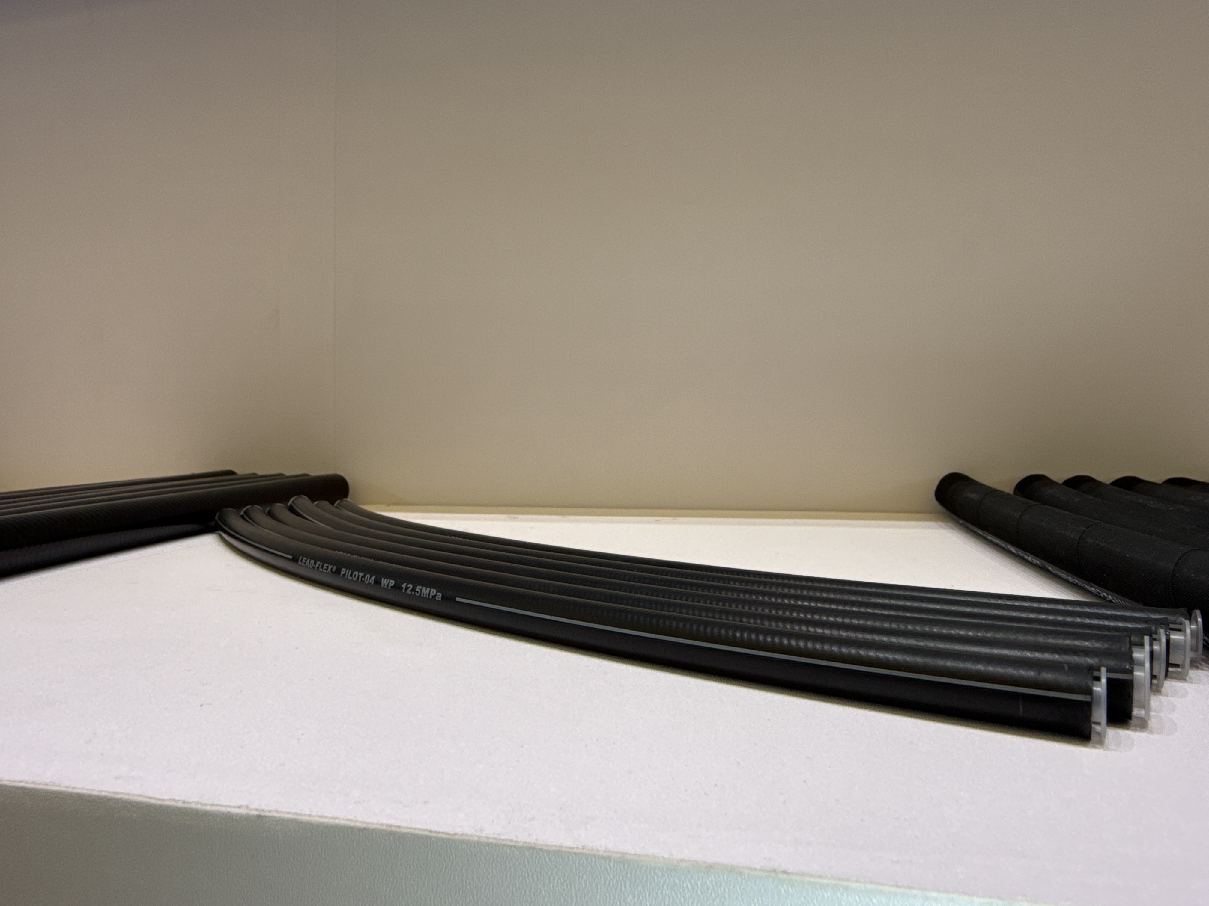
Pilot hydraulic lines function as the critical nervous system of modern heavy machinery. Sizing them incorrectly leads to sluggish control responses, localized heat buildup, and unpredictable valve actuation. This creates significant operational risks and inefficiencies on demanding job sites. Primary power hoses prioritize high-volume fluid flow to drive massive cylinders. Conversely, a pilot control hydraulic hose prioritizes rapid, precise pressure signal transmission. You need instant, reliable communication between the operator's cabin joystick and the main control valve bank. We will establish clear engineering criteria to specify the correct inside diameter (ID) bore size for these systems. You will learn how to balance fluid dynamics, navigate physical routing constraints, and ensure strict compliance with OEM tolerances. Choosing precise dimensions guarantees operational precision, reduces operator fatigue, and extends system longevity.
Key Takeaways
Pilot hydraulic hoses typically require small bore sizes—most commonly 1/4-inch (-4 Dash) or 3/8-inch (-6 Dash) inside diameter (ID).
Undersizing the bore causes excessive pressure drops, leading to slow attachment responses and heat generation.
Oversizing the bore adds unnecessary weight, complicates routing in tight spaces, and can create marginal delays in signal transmission.
The optimal spec balances precise ID dimensions with a flexible, high-durability construction, such as a compact single wire hydraulic hose, to manage tight bend radii.
The Engineering Function of a Pilot Control Hydraulic Hose
Defining the fundamental difference between power lines and pilot lines remains crucial for proper system design. Power lines actuate massive external components, such as boom cylinders or track motors. They require huge fluid volumes moving at high velocities to perform physical work. Pilot lines perform a completely different, highly specialized job. They shift tiny metal spools inside directional control valves. Think of a Pilot Hydraulic Hose as a high-speed communication cable rather than a heavy-duty power cord. It transmits an operator's physical command into a hydraulic command.
Pilot systems operate at a tiny fraction of main system flow rates. They typically run well under 5 gallons per minute (GPM), and often less than 2 GPM. However, they require instant pressure stabilization to function correctly. When you move a joystick, the pilot fluid must reach its targeted operating pressure immediately. This instantly shifts the main valve spool against its internal return spring.
The physics of fluid column movement dictate your bore size choice. An oversized bore holds an excessive volume of hydraulic oil. The pilot pump must fill this extra internal space and compress the fluid slightly before pressure actually builds at the valve end. This causes micro-delays in joystick response, making the machine feel laggy. Conversely, an overly tight bore heavily restricts fluid movement. This chokes off the pressure signal entirely, causing the machine to ignore slight joystick inputs.
Standard Bore Sizes and the Dash Size System
The fluid power industry universally uses the dash system to measure hose inside diameters. This system measures the inside diameter (ID) in increments of 1/16ths of an inch. A -4 hose indicates a 4/16-inch measurement. This simplifies to 1/4 inch, or approximately 6.4mm. We apply this standardized system universally across all pilot line specifications to ensure global compatibility.
The 1/4-inch bore remains the absolute industry baseline for the vast majority of pilot applications. It offers the ideal internal fluid volume for rapid pressurization. It delivers excellent pressure transmission speed from the cabin to the control block. Furthermore, the small outside diameter provides exceptional routing flexibility inside cramped operator cabins and under tight floor panels.
Sometimes you must deviate from this standard baseline. Larger excavators, forestry equipment, or extended machinery booms require significantly longer hose runs. Moving hydraulic fluid over these greater distances exponentially increases internal fluid friction. We step up to a -6 size, which equates to a 3/8-inch ID (approximately 9.5mm), in these specific scenarios. This size increase successfully mitigates friction-induced pressure drops over distance.
Manufacturing tolerances for the inner and outer diameters must remain incredibly strict. Pilot fittings demand extreme precision to seal correctly at moderate pressures. If a hose ID fluctuates even slightly beyond accepted ISO or SAE tolerances, you risk improper crimping. This can lead to weeping leaks or completely blowing off the high-precision pilot fittings during pressure spikes.
Analyzing Pressure Drop and Control Responsiveness
An undersized bore acts exactly like a traffic bottleneck on a busy highway. It creates massive fluid friction as oil forces its way through the narrow passage. This internal friction drastically reduces the pilot pressure before it ever reaches the main spool valve. Consequently, the main valve shifts slowly, or sometimes incompletely. Operators experience this directly as sluggish, unresponsive attachment movements. A bucket may curl too slowly, or a swing motor might hesitate before engaging.
Restricted fluid flow does much more than just delay operational signals. Forcing pilot fluid through a restricted, undersized bore creates intense localized heat. Hydraulic oil temperatures spike rapidly at the restriction point due to shear friction. This constant thermal stress degrades the inner synthetic rubber tube material prematurely. Over time, the rubber hardens, cracks, and introduces physical contamination into the sensitive pilot circuit.
You must factor in multiple variables when finalizing your bore size trade-offs. You can evaluate the optimal size by following a structured calculation approach:
Determine Total Hose Length: Measure the exact distance from the pilot controller to the directional valve. Runs over 15 feet may require stepping up a size.
Evaluate Fluid Viscosity: Identify the standard operating temperature. Cold environments thicken hydraulic oil, increasing viscosity and friction.
Assess Valve Spool Resistance: Check the OEM specifications for the pilot pressure required to fully shift the main directional valve.
Calculate Acceptable Pressure Drop: Ensure the pressure at the end of the line remains above the valve's minimum actuation threshold, even under cold start conditions.
Pilot System Bore Size Trade-off Analysis
Design Factor
-4 Dash (1/4" ID) Impact
-6 Dash (3/8" ID) Impact
Pressure Drop
Higher resistance over long distances
Minimal resistance over long distances
Signal Speed
Fastest, crispest operator response time
Slight micro-delays possible due to volume
Routing Flexibility
Excellent bend radius for tight cabins
Moderate bend radius, stiffer handling
Heat Generation
Higher risk if fluid flow is restricted
Lower risk of localized friction heat
Evaluating Hose Construction for Pilot Applications
Pilot lines must navigate brutally tight, complex spaces. They snake through densely packed machine cabins, route under pedals, and wrap around dense, multi-port valve manifolds. Therefore, dynamic bend radius becomes a highly critical evaluation metric during the selection process. Stiff, bulky hoses simply will not bend tightly enough without kinking or stressing the fitting connections.
A compact single wire hydraulic hose meets these specific routing challenges perfectly. Industry specifications like EN857 1SC provide the ideal balance of strength and agility. They are notably lightweight and incredibly flexible, allowing for tight installation radii. They also easily handle standard pilot system pressures, which typically operate between 300 and 1,000 PSI, though these hoses often boast maximum ratings up to 3,000 PSI.
Some pilot systems share routing channels or external manifolds with high-flow main pressure lines. These exposed areas subject the pilot lines to severe external mechanical abrasion, flying debris, and sudden adjacent pressure spikes. In these aggressive environments, you should immediately upgrade to a High Pressure Steel Wire Braided Hose. The two-wire (2SN) construction provides essential structural armor, preventing crushing impacts and abrasive wear from destroying the line.
Do not ignore the outer cover material during your evaluation. You should select the jacket material based strictly on the operating environment:
Standard Synthetic Rubber: Ideal for protected internal cabin routing where UV and abrasion risks remain very low.
Wrapped Cover: Provides slightly better grip and traditional durability for standard under-hood equipment routing.
UHMWPE (Ultra-High Molecular Weight Polyethylene): Strongly recommended where hoses rub constantly against chassis steel, concrete, or other hoses. This jacket prevents premature external wear.
Implementation Risks, Fittings, and Rollout Considerations
Mismatching bore sizes with incorrect fittings causes catastrophic field failures. Pilot systems operate at moderate pressures, but they are not immune to blow-offs. Low-pressure push-lok systems might handle low-pressure pilot returns safely. However, primary pressure pilot lines strictly require traditional, permanently crimped fittings. Always verify the manufacturer's specific crimp diameter specifications for your chosen hose inner diameter to ensure a permanent mechanical seal.
Pilot control valves feature incredibly tight internal spool tolerances, often measured in microns. Because of this, they are highly sensitive to microscopic debris. When cutting bulk hoses to size, abrasive saw dust and rubber particles inevitably enter the bore. You must flush the newly cut hose thoroughly with a specialized pneumatic cleaning projectile before attaching any fittings. Skipping this vital cleanliness step sends abrasive debris directly into expensive pilot valves, causing them to jam or score.
Air is a compressible gas, whereas hydraulic oil is an incompressible liquid. If you trap air pockets in small-bore pilot hoses during installation, the air compresses every time you move the joystick. The fluid movement energy goes into compressing the air bubble rather than shifting the valve. This causes severely spongy, unpredictable, and erratic control behavior. You must meticulously bleed all trapped air from the pilot circuit at the highest point after replacing any lines to restore crisp machinery operation.
Conclusion
Selecting the right pilot line requires following a strict, logical progression to ensure machinery safety and efficiency. First, identify the exact OEM flow and pressure requirements for the pilot circuit. Next, select the -4 or -6 Dash size by factoring in the total hose length and the fluid viscosity expected in your operating climate. Then, choose your internal construction based on routing tightness. Lean toward a flexible compact single wire for tight spaces or a rugged standard two-wire braid for exposed areas. Finally, rigorously verify fitting compatibility before crimping.
Never rely on guesswork when dealing with heavy machinery controls. As a best practice, encourage your maintenance teams to consult the equipment’s factory hydraulic schematic for precise operating parameters before ordering replacement assemblies. Taking these proactive verification steps guarantees smoother machine operation, faster attachment response times, and fewer unexpected breakdowns in the field.
FAQ
Q: Can I use a -6 (3/8") hose to replace a -4 (1/4") pilot line?
A: It is generally not recommended. While sizing up may reduce pressure drop, the increased internal fluid volume changes system dynamics. This extra volume alters the timing and responsiveness of the pilot signal. Operators often experience this as spongy, imprecise, or noticeably delayed joystick controls. Always stick to the OEM bore size unless re-engineering for specific long-run applications.
Q: Are push-lok fittings safe for pilot hydraulic hoses?
A: Push-lok fittings are typically rated strictly for low-pressure applications, usually under 300 PSI. Many modern pilot systems operate at higher ranges, often between 300 and 1,000 PSI. Because of these higher working pressures, using highly secured crimped fittings on a High Pressure Steel Wire Braided Hose remains the safer, industry-standard practice for primary pilot lines.
Q: How does temperature affect the bore size decision for pilot lines?
A: In extremely cold operating environments, hydraulic fluid viscosity increases significantly. The oil becomes thick and sluggish. A slightly larger bore size, or a hose specifically formulated for low-temperature flexibility, may be required to prevent sluggish controls during startup. Without this accommodation, the cold, thick fluid experiences severe pressure drops due to friction inside standard small-bore hoses.