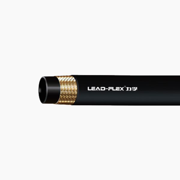
Replacing or installing a hydraulic hose is never a guessing game. A fraction of an inch in miscalculation can lead to catastrophic blowouts. It also triggers severe system pressure drops and forces machinery offline. Fluid systems demand absolute precision to avoid dangerous, high-pressure leaks.
You might be routing an entirely new fluid power system. Or, you might just be replacing a single failed assembly. Accurate measurement ensures your fittings seat correctly every single time. Precise sizing also guarantees the hose maintains absolute structural integrity under peak operating pressure.
This guide provides a definitive, step-by-step framework for measuring hydraulic lines properly. We carefully differentiate between overall length and cut length. You will ultimately learn how to verify exact dash sizes for accurate, risk-free procurement.
Key Takeaways
Inside Diameter (ID) dictates flow: Always measure ID to determine the correct "Dash Size" and prevent system overheating or pressure loss.
OAL vs. Cut Length: Overall Length (OAL) includes the fittings, while Cut Length subtracts the fitting cut-off factors to determine the actual hose required.
Bend radius is non-negotiable: Accurate measurement must account for the minimum bend radius; routing too tightly degrades wire reinforcement and guarantees early failure.
Precision tools matter: Rely on digital calipers and specialized thread gauges rather than standard tape measures for OD and fitting measurements.
The Operational Cost of Incorrect Hose Measurement
System Inefficiencies
Undersized hoses restrict fluid flow immediately. This restriction increases fluid velocity significantly inside the line. High velocity creates immense friction along the inner tube. Friction leads directly to system overheating. Overheated oil loses essential lubricating properties rapidly. Pumps often experience cavitation under these restricted conditions. Cavitation destroys internal pump components over time. You must match the exact flow requirements to maintain system efficiency.
Premature Assembly Failure
Hoses cut too short endure extreme axial stress. They pull violently against fittings when pressurized. Hoses can contract by up to 4% under maximum working pressure. This dramatic contraction rips fittings right off the hose. Axial tension also degrades the internal wire reinforcement. We constantly see premature failures linked directly to tension. You must always incorporate adequate slack to absorb pressure shocks.
Routing Hazards
Hoses cut too long create entirely different operational problems. They hang loose and rub against metal machine frames. This extra slack invites severe exterior cover abrasion. Exposed wire reinforcement quickly rusts and fails. Long lines also kink easily during machine operation. They easily catch on moving machinery components. A caught line will rip apart instantly under mechanical force.
Safety and Compliance Risks
Improperly measured lines cause severe workplace accidents. Poorly crimped assemblies blow out violently under load. These unexpected blowouts remain the leading cause of high-pressure fluid injection injuries. Injection injuries require immediate, specialized surgical intervention. Ruptured lines also trigger massive environmental oil spills. Regulatory bodies issue heavy fines for preventable environmental contamination. Accurate measurement fundamentally protects your workforce and your compliance record.
The fluid power industry relies entirely on the Dash Size system. This system standardizes hose sizes globally. A single dash represents one-sixteenth of an inch. For example, a -4 size equals 4/16, or 1/4 inch. A -8 size translates to 8/16, or 1/2 inch. You determine the dash size by measuring the inside diameter (ID). Use digital calipers to measure the ID precisely. Proper ID ensures accurate fluid volume matching. Too small of an ID creates dangerous heat. Too large of an ID reduces system responsiveness.
Outside Diameter (OD)
The outside diameter (OD) dictates ferrule and fitting compatibility. You must measure OD accurately to select the correct crimp shell. A mismatched ferrule will never secure the fitting properly. We often compare standard SAE 100R1 hoses to modern alternatives. A compact single wire hydraulic hose provides a distinct advantage here. Compact hoses feature significantly thinner outer covers. They allow tighter routing spaces inside crowded engine compartments. They achieve this without sacrificing maximum pressure ratings. Always verify the OD before attempting any crimping procedure.
Overall Length (OAL)
Overall Length (OAL) represents the total span of the finished assembly. It is the exact distance from the extreme end of one fitting to the extreme end of the other. Straight fittings are simple to measure edge to edge. Angled fittings require a different approach entirely. You must measure angled fittings to the center of the sealing surface. This center-point measurement ensures accurate installation on the machine. Ignoring this rule guarantees your new assembly will not fit.
Industry Sizing Reference Table
Dash Size
Fractional Equivalent (Inches)
Typical Inside Diameter (mm)
-4
1/4"
6.4 mm
-6
3/8"
9.5 mm
-8
1/2"
12.7 mm
-10
5/8"
15.9 mm
-12
3/4"
19.0 mm
-16
1"
25.4 mm
Step-by-Step: Calculating OAL vs. Cut Length
Step 1: Determine the Required Overall Length (OAL)
Route a flexible measuring rope along the exact physical path on the equipment.
Follow the natural contours of the machine frame carefully.
Incorporate necessary slack to accommodate regular mechanical movement.
Add a 4% length allowance specifically for pressure contraction.
Mark the extreme end points where the fittings will connect to the ports.
Measure the rope on a flat surface to find your total required OAL.
Step 2: Identify the Fitting Cut-Off Factor (C-Dimension)
The cut-off factor is a critical measurement for custom assemblies. It represents the length of the fitting extending beyond the raw hose end. This applies only once the fitting is fully crimped. You must account for this extra length to avoid making the assembly too long. Manufacturers provide specific C-dimensions for every fitting style.
Use this precise formula to find your actual cutting mark: Cut Length = OAL - (Cut-Off Factor A + Cut-Off Factor B).
For example, imagine your OAL is 50 inches. Fitting A has a 1-inch cut-off factor. Fitting B has a 1.5-inch cut-off factor. You subtract 2.5 inches from 50. Your exact cut length is 47.5 inches. Always verify these factors using technical data sheets.
Step 3: Account for Angle and Orientation
Angled fittings demand careful physical alignment before crimping. Suppose you use two 90-degree elbows on a single line. You must measure their orientation angle relative to each other. Technicians usually express this angle in degrees. Poor orientation forces you to twist the hose during installation. Twisting ruins the structural integrity of a Braided Hydraulic Hose. A mere 7-degree twist can reduce assembly lifespan by 90%. Use a chalk line along the outer cover to track alignment. Secure the fittings in a vise to maintain the correct angle during the crimp.
Evaluating Bend Radius and Routing Allowances
Defining Minimum Bend Radius
Minimum bend radius is an absolute physical limit. It represents the smallest radius the hose can handle safely. Bending past this critical limit causes immediate kinking. Kinking flattens the internal tube and restricts flow. It also heavily stresses the single wire braid reinforcement. The steel wires stretch on the outside curve. They bunch together on the inside curve. This distortion guarantees rapid metal fatigue. Always reference the manufacturer specification for minimum bend radius. Never guess this metric.
Routing Best Practices
Proper routing extends the life of your fluid power system drastically. Follow these proven industry guidelines:
Avoid bending the line immediately behind the metal fitting.
Allow a straight length of at least 1.5 times the hose OD right at the connection.
Use appropriate steel adapters to prevent sharp bends.
Install 90-degree block fittings to handle tight corners cleanly.
Secure long runs using insulated clamps to prevent vibration damage.
Route lines parallel to machine contours for better protection.
Measuring for Dynamic vs. Static Applications
Dynamic applications require extra attention during the measurement phase. Cylinders and hydraulic booms articulate constantly during operation. You must add precise slack to accommodate this full range of motion. Measure the required length at both fully extended and fully retracted positions. Static applications are much simpler. They only require standard pressure-contraction slack. Do not add excessive length to static lines. Excess length only creates unnecessary abrasion risks.
Shortlisting and Selecting the Right Braided Hydraulic Hose
Matching Specs to the Application
You must ensure the measured hose meets all system requirements. Check the maximum operating pressure limits carefully. The hose rating must exceed the highest pressure spike of the system. Verify the specific temperature requirements of the hydraulic fluid. Some synthetic fluids run extremely hot. Reference global manufacturing standards like ISO, SAE, and DIN. Always select a reputable single wire braided hydraulic hose for standard pressure applications. Proper specification matching prevents catastrophic field failures.
Cover Material Requirements
Assess your operational environment thoroughly before purchasing. Look closely for extreme abrasion risks. Check for continuous UV exposure outdoors. Evaluate the presence of harsh industrial chemicals. Determine if a standard synthetic rubber cover works for your needs. Sometimes, you need an ultra-abrasion-resistant cover instead. High-abrasion covers utilize specialized polymer blends. These tough covers eliminate the need for secondary protective sleeves. They save significant time during final installation.
Vendor Evaluation Criteria
Choosing the right supplier is just as important as measuring correctly. Look for fully transparent manufacturing suppliers. They must provide clear, accessible technical data sheets (TDS). Ask them for exact C-dimension charts for all their fittings. Demand batch-tested assemblies to ensure optimal safety. Reliable vendors perform regular impulse testing on their products. Impulse testing verifies long-term durability under rapid pressure changes. Avoid vendors who refuse to share detailed crimp specifications.
Conclusion
Accurate measurement forms the true foundation of a safe, reliable system. Leak-free hydraulics require absolute precision at every single step. Mastering inside diameters, cut-off factors, and routing physics actively mitigates costly downtime. A properly measured assembly easily survives harsh operating environments.
We recommend consulting a certified fluid power specialist today. You should always utilize manufacturer sizing charts before cutting any bulk stock. Verify all your physical measurements twice before ordering custom-crimped assemblies. Precision today prevents catastrophic failure tomorrow.
FAQ
Q: How do I measure a blown or damaged hydraulic hose?
A: Do not measure the damaged section if it is stretched or deformed. Measure the exact routing path on the machine instead. Alternatively, assemble the broken pieces on a flat surface. This helps you estimate the original overall length (OAL). Always ensure you verify the C-dimensions of the attached fittings before cutting replacement stock.
Q: Can I use any brand's fittings on a single wire braided hydraulic hose?
A: No. Mixing hose and fitting brands voids warranties immediately. It also poses a severe safety risk. Wall thickness and crimp specifications vary significantly by manufacturer. Always use fittings explicitly cross-certified for your specific hose brand to guarantee a secure, leak-free crimp under maximum system pressure.
Q: How much length should I add to account for hose contraction under pressure?
A: A general industry rule applies here. Allow for up to a 4% contraction in overall length. You should also account for up to 2% elongation. This dimensional change occurs when the hose reaches its maximum working pressure. Always ensure your final measurement includes adequate slack to prevent axial stress.